Limit switches (also known as end stops) are a simple, cheap and useful addition to any CNC machine. However, as a beginner I overlooked them. I later learned my mistake, as these small unassuming guys can save time and even prevent costly accidents. However, it takes a few steps to set them up properly, so let’s see how to do it.
Why use limit switches?
A limit switch is a way of physically detecting when an axis reaches the limit of its travel and automatically stop the machine. This has a few uses:
- Prevent skipped steps or even damage to the frame, motors, or other parts of the machine.
- To enable homing on each axis.
What is homing?
Homing is a way for the controller to reliably know the physical location of the gantry. This works by slowly moving each axis until they trigger a limit switch, which marks the zero position. This way, even if after shutting down the machine or if the motors skip steps, re-homing will restore the correct coordinates.
With limit switches, the firmware will keep track of at least two separate coordinate systems:
- The Machine coordinate system, representing the toolhead position across the entire working area;
- One or more Work coordinate systems (WCS), which are set manually. G-code move commands are interpreted according to this coordinate system.
(Grbl supports up to six work coordinate systems, which can be toggled with G54 through G59)
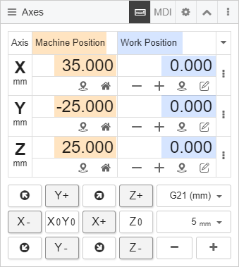
CNC.js displays the toolhead position in both coordinate systems: machine coordinates and work coordinates
How many switches per axis?
Each axis of a CNC machine can have zero, one, or two limit switches installed.
While it’s generally a good idea to use limit switches, it’s not strictly necessary, and many hobby machines don’t come with them installed.
With one switch per axis, you get homing and overtravel detection on only one direction per axis. However, Grbl, Marlin and other controller firmwares are able to stop an axis even in the other direction by keeping track of the steps made. This feature is called soft limits.
However, soft limits are only reliable if the motors don’t lose any steps. That’s why two physical switches on each axis are preferable.
Types of limit switches
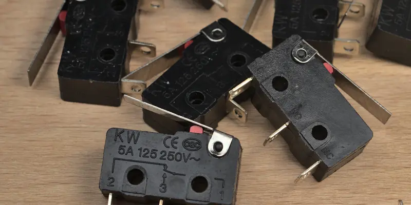
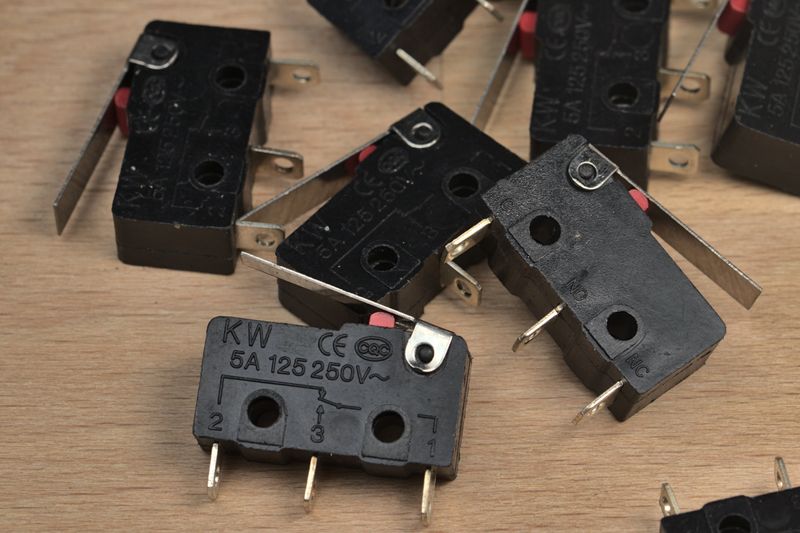
Lever switch (bare)

These are SPDT (single pole, double throw) momentary switches. This means they switch one input (pole) between two output (throws). They have three pins (the order varies depending on the switch model): common (C / COM), normally open (NO), and normally closed (NC).
Later on we’ll see how to wire these switches and which pins to use.
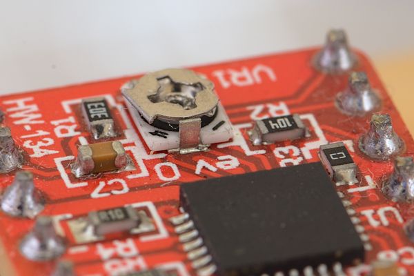
Lever switch (on a breakout board)
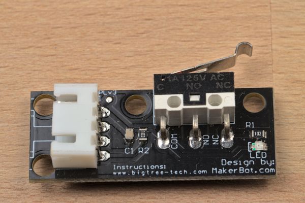
Breakout board with lever switch
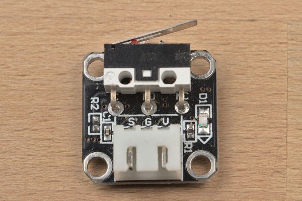
Breakout board with lever switch
Sometimes, the switch is soldered onto a PCB. These are convenient as they include a JST connector, mounting holes, an LED indicating whether the status of the switch, and a 0.1 uF ceramic capacitor (probably for debouncing).
However, the two breakout boards I’ve used only work when wired normally open (more on this later).
Inductive proximity switch
An inductive proximity switch
Inductive switches are great because they don’t even need to touch the surface they’re detecting. They are triggered when they are close to a conductive material, for example aluminum.
They have three pins: two for power (6-36V and ground) and one for the signal, which is read by the microcontroller.
Hall effect switch
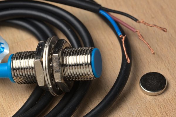
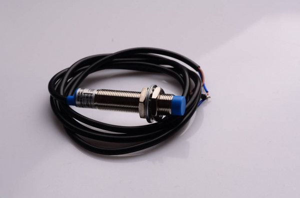
NJK-5002C hall effect proximity switch
Hall effect switches are contactless sensors, like inductive switches. However, hall effect are triggered only when a magnet gets close, because they work by sensing its magnetic field. More specifically, these are digital hall effect sensors, meaning they either fully open or close. (More uncommon models are analog and vary the output voltage gradually between 0V and the supply voltage.)
The hall effect switches I’m using (NJK-5002C) work at 5V and are triggered when the included magnet is under ~3/8” (~10mm) away. You can get them here: NJK-5002C. The threaded enclosure and included nuts make it very easy to mount them to the frame of a machine, and precisely adjust the detection distance to the gantry.
They have three wires: brown is for VCC, blue is ground, and black is the output signal (which is either 0V or close to VCC).
Limit switch wiring
I’ll cover how to wire the lever limit switches, as they are the most commonly available.
Normally open vs normally closed
Most limit switches have three pins:
- One common (C or COM) pin, which goes to the machine.
- One normally open (NO) pin, which is connected to the common pin only when the switch is pressed.
- One normally closed (NC) pin, which is connected to the common pin only when the switch is not pressed.
Limit switches can be wired normally closed or normally open, depending on which pin you connect. The common pin is always connected to the controller. Polarity doesn’t matter, since the switch simply shorts the controller pin to Ground.
Commonly closed is the preferred wiring. It provides protection against noise, and in case of failure (a broken switch or severed wire), the machine would automatically stop.
In order to home with NC switches, Grbl needs to be configured with the $5=1 command.
On the other hand, normally open switches usually work out of the box with any firmware including Grbl.
Warning: the switches on the breakout boards I have only seem to work when wired normally open. This is because they have a 10K resistor through the normally closed pins (used for the LED), so the Arduino does not see the pins as closed.
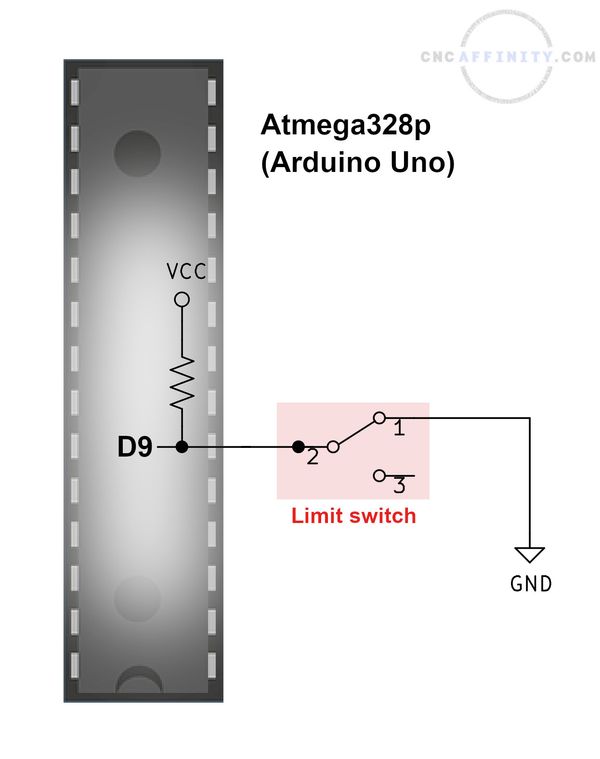
Why a pull-up resistor is needed
Before wiring everything up, let’s have a look at how a microcontroller even detects if the switch is triggered.
If a switch is wired normally open, there is no connection between the two pins on the controller. In this situation, usually the controller will detect 5V on that pin (or whatever is its supply voltage), because a resistor (usually inside the chip) is used to safely hook up the pin to 5V. This is called a pullup resistor. This resistor can be enabled or disabled by the firmware (Grbl has it always enabled by default).
If a switch is wired normally closed, the state is reversed and the controller normally reads 5V through that pin.
When the switch is closed, the controller pin is shorted to ground. When the switch is open, a resistor allows the pin to be connected to the supply voltage without damaging the pin.
If the pin were connected directly to 5V without a resistor, it would damage the chip. If there were no connection to 5V or Ground at all, the pin would be “floating”, meaning the pin would pick up the electromagnetic noise around rather than reading 0V. The Atmega328p on the Arduino Uno uses a 47k ohm resistor.
Note that (as of writing) the official Grbl documentation is out of date. Up to version 0.8, inverting the switch behavior caused Grbl to disable the internal pull-up resistors, but this is not the case anymore:
NOTE: If you invert your probe pin, you will need an external pull-down resistor wired in to the probe pin to prevent overloading it with current and frying it.
Indeed, the official wiring guide does not mention any pull-down resistors.
Connecting pins
In the case of bare switches, you can solder the wires directly to the pins with heat shrink, but a cleaner way is to use proper female spade connectors.
This set of crimp connectors includes spade connectors of different sizes as well as other useful crimp connectors like “butt” connectors that can help with extending stepper motor wires and fork connectors which are the best way of attaching wires to screw terminals.
Switches mounted onto breakout boards come with 2.54mm (1”) JST-XH connectors. In order to make your own cable, you’ll need a crimper and a set of JST-XH crimps and housings .
I recommend the Iwiss 2820 crimper which I got upon Andreas Spiess’s recommendation. It can crimp wire between 28 and 20 AWG (Iwiss also makes a crimper for 24-12 AWG ).
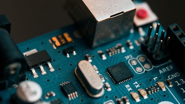
Wiring: Arduino Uno
The official Grbl wiring guide does a great job showing how to wire the limit switches to an Arduino Uno. This is the pinout:
| Arduino Uno pin | Axis |
|---|---|
| D9 | X |
| D10 | Y |
| D11 (Grbl < 0.8) | Z |
| D12 (Grbl >= 0.9) | Z |
There’s a catch with the Z pin: with Grbl 0.9 it was moved from D11 to D12. More on this later.
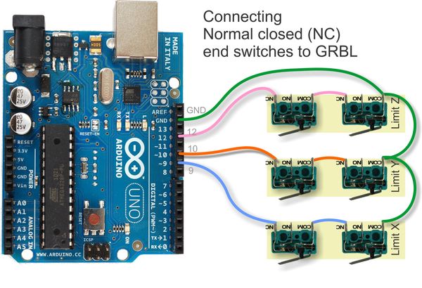
Wiring diagram: normally closed switches (source)
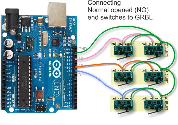
Wiring diagram: normally open switches (source)
Wiring: CNC shield
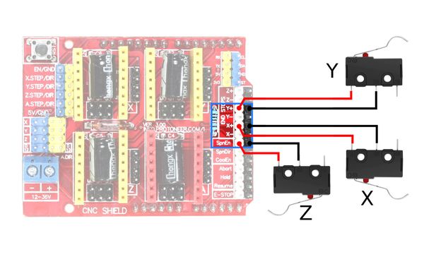
Limit switch wiring for the CNC shield. Make sure the common pin of each switch is connected to the shield.
The CNC shield has six pairs of pin headers dedicated to the limit switches: X-, X+, Y-, Y+, Z-, Z+ and a ground pin for each.
In reality, X- and X+ share the same Arduino pin (D9) and the same is true of the Y and Z pairs. This is done to save Arduino pins. As a result, when either limit switch assigned to one axis is triggered, Grbl can’t actually tell which one was triggered.
How to fix: Grbl Z limit switch not working
There’s a catch when using Grbl 0.9 or above with the CNC shield.
Depending on how you wire your limit switches, the Z limit switch may not work. The reason is that Grbl 0.9 swaps the Z-limit pin (D11 on the Uno) with the spindle control pin (D12). This was done in order to add PWM control for the spindle (D12 doesn’t support PWM, but D11 does).
We need to wire the Z-limit switch to the spindle enable pin (SpnEn), or alternatively to the D12 pin. If you have two Z switches, you can wire one to each pin or wire them together in series.
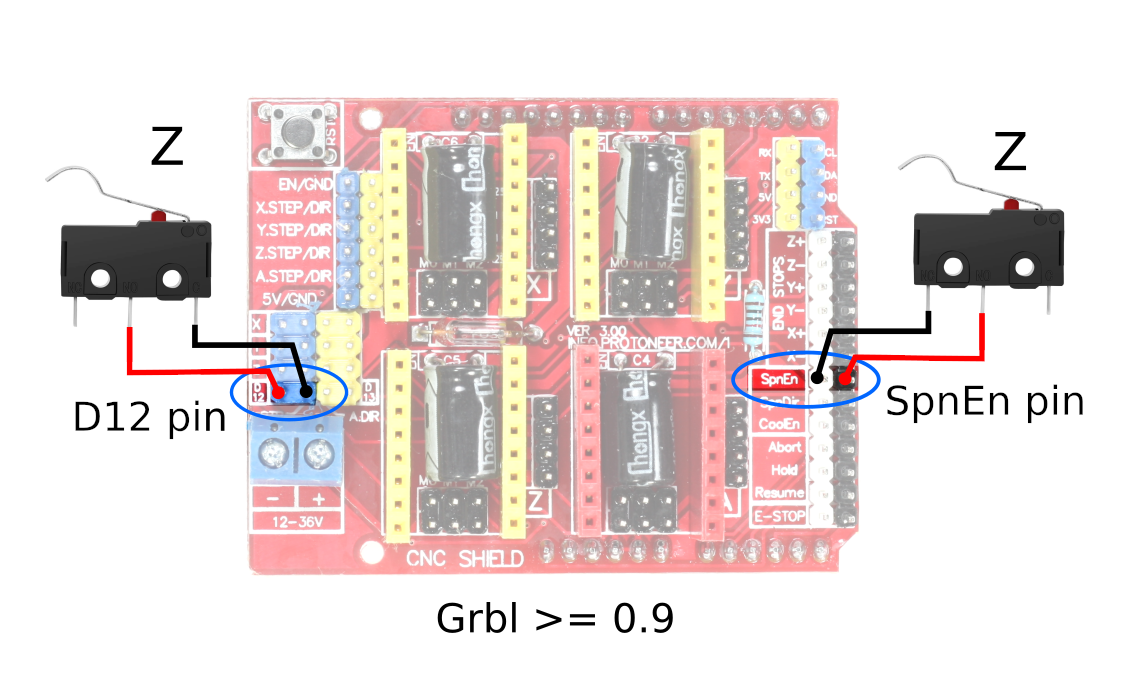
Wiring the Z limit switches on Grbl 0.9 or above.
Alternatively, there is also a software workaround that lets us use the correctly labeled pins. We’ll have to change a line in the Grbl source code and then reflash the Arduino.
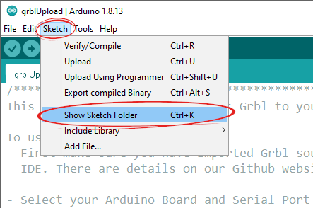
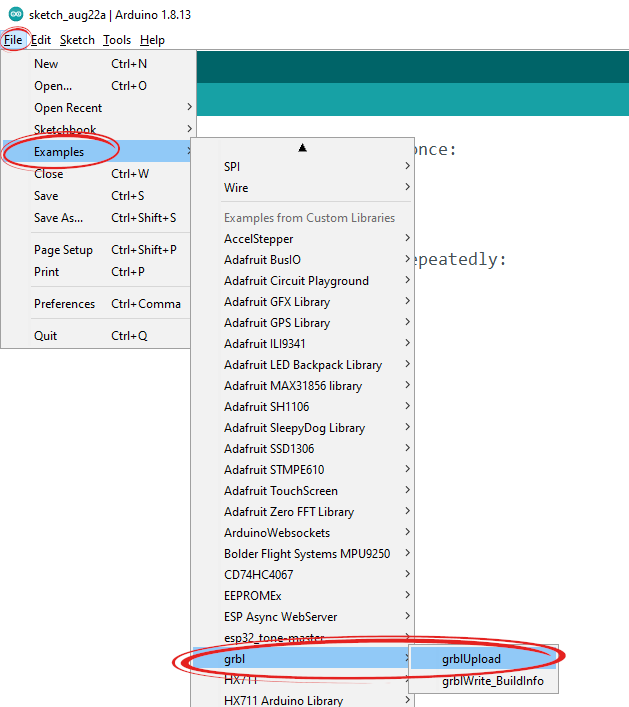
First let’s open the Grbl folder. Load the grblUpload example sketch (File > Examples > grbl > grblUpload), and open the folder (Sketch > Show Sketch Folder).
We’ll need to change config.h. You can open it with any text editor such as Notepad, TextEdit or VS Code.
Scroll down to line 339, or search (ctrl+F) for #define VARIABLE_SPINDLE. This is the line we need to change:
#define VARIABLE_SPINDLE // Default enabled. Comment to disable.
Comment out this line by adding two slashes at the start of this line, then save the file:
// #define VARIABLE_SPINDLE // Default enabled. Comment to disable.
Now just reupload Grbl to the Arduino using the grblUpload example, and we’re done.
Using optocouplers to avoid EMI
Electromagnetic interference (EMI) can cause the controller to behave unpredictably. If your limit switches appear to be triggered at random occasions, it’s probably an EMI issue. Normally open switches are especially prone to EMI.
One solution is to use optocouplers (also known as photo-isolators) to electrically isolate the switch side from the controller side. They work by using an infrared LED and a photoresistor to carry a signal through light only, thus avoiding noise.
The Grbl wiring page has diagrams for optocoupler wiring. Alternatively, a similar board is available here on Tindie.
Enabling limit switches and homing in Grbl
Simply wiring the switches to an Arduino or CNC Shield won’t be enough. We also need to enable them in the firmware with a number of commands.
Grbl settings
With your controller plugged in, open up any G-code sender you like and type $$ into the console to display the current Grbl settings. I recommend using UGS Platform or CNC.js, as they include descriptions for each command (Grbl 1.1 omits them due to insufficient storage).
The Arduino IDE’s serial monitor can also be used instead of a G-code sender.
These are the main commands to set up limit switches and homing (the official documentation has the full list of commands):
| Command | Usage |
|---|---|
| $5=0 | Treat switches as normally open |
| $5=1 | Treat switches as normally closed |
| $20=1 | Enable software limit |
| $21=1 | Enable physical limit switches |
| $22=1 | Enable homing |
| $130=N | Set the X soft limit to N mm |
| $131=N | Set the Y soft limit to N mm |
| $132=N | Set the Z soft limit to N mm |
| $X | Unlock the machine |
| $H | Home the machine |
- First off, we’ll need to send the
$21=1command to enable the switches. - If you are running only one switch per axis, you’ll want to enable soft limits with
$20=1and set the travel for each axis in mm. For example$132=50sets the Z axis max travel to 50mm (2”). - In order to use the switches for homing, enable it with
$22=1. - If your switches are wired normally closed, you’ll need to set
$5=1.
Homing a Grbl machine
With homing enabled, when you power on your Grbl controller it will throw an alarm. This is a warning that the machine has not been homed.
First, we need to unlock the machine with
$X.Then, homing is done by sending the
$Hcommand ($X and $H are specific to Grbl).
Every time you power on the machine, it has to be homed, party because the machine coordinate system doesn’t persist after a shutdown, but especially because an unpowered machine can’t track the gantry position. Homing the machine at the start guarantees that the coordinate system correctly matches the physical location of the toolhead.
If for some reason you really want to disable the homing warning, you’ll have to comment out line 230 of Grbl’s config.h and reflash it (see the previous section ):
// #define CHECK_LIMITS_AT_INIT
Grbl homes the Z axis first, then X and Y together.