Freecad users have a few choices when it comes to rendering their 3D models. While Freecad has its own Render workbench, using an external renderer has its own benefits.
The easiest to use rendering program is probably CADRays (you can read my tutorial here) , but there’s no doubt that Blender is much more capable and widely used, and more suitable for complex scenes.
For this guide, I’ll cover how to create a basic render in Blender, and then I’ll go through a few extra tips and settings to make the lighting more realistic and further improve our final result.
Basic guide
Blender can be downloaded for free from this page.
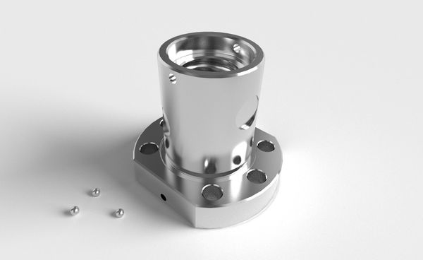
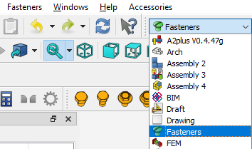
For this tutorial, I’ll be rendering a set of screw and nut made with Freecad’s Fasteners workbench. If you don’t have it, you can enable it from Tools > Addon manager > Install/update selected. Then switch to the Fasteners workbench and add the screws with Fasteners > Add Fasteners.
Naturally, you can use your own models instead or you can import a step (.stp / .step) file into Freecad.
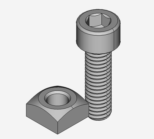
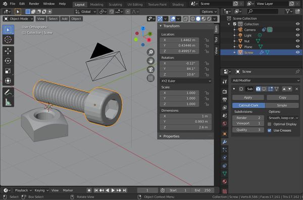
Our model in Freecad
If you need to move a body around in Freecad, use right click > Transform and move it by dragging the colored axes.
1. Exporting our Freecad model
Freecad uses its own FCStd format, which we cannot import directly into Blender. We also cannot import a step file. Instead we have to export our model as an STL, OBJ, or any other tessellated format.
Unfortunately, these formats have a drawback: they approximate curves using flat faces. Later in the tips & tricks section of this tutorial I explain how to export a high quality STL to minimize this issue.
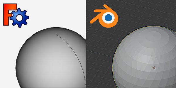
Blender and any tessellated format like STL approximate curves using flat faces.
To save our Freecad project for use in Blender, select all bodies you want to export and click on File > Export…, then select your preferred format. We have a few options here:
- STL (also typically used for 3D printing; it stores geometry information only)
- OBJ (used mostly for computer graphics; it supports both geometry and textures)
- DAE also known as Collada
STL and OBJ have one major issue: every shape is treated as a single object, even if physically separate. Here’s what this means: if you have two separate bodies in Freecad, and you export them as a single STL/OBJ, Blender will see everything as a single object. This is not Blender’s fault, but a limitation of these formats.
In our example scene, the bolt and nut, which were separate objects inside Freecad, are merged into a single mesh inside Blender:
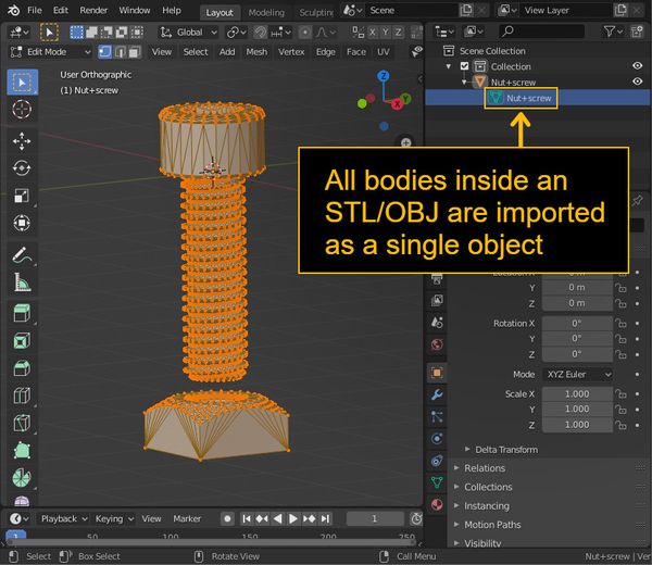
If we export our nut and bolt as an STL or OBJ, they are merged into a single mesh.
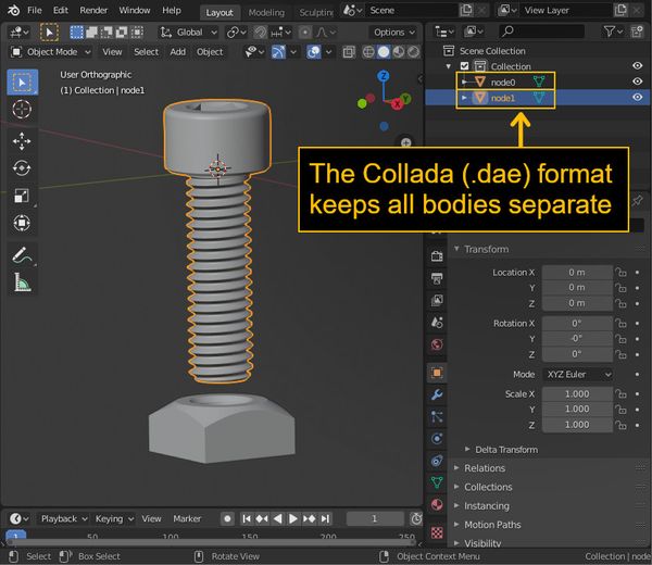
The solution to this problem is to use a multi-object format like Collada (DAE), which is what I recommend using unless you are exporting a single body.
2. Importing into Blender
The default scene in Blender has a cube, a camera and a light source. We don’t need the cube, so left click on it and press X to delete it.
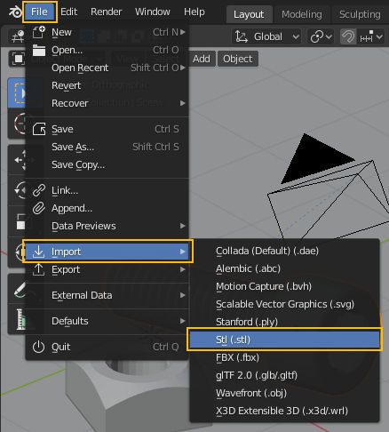
Then import our STL, OBJ or DAE file into Blender: File > Import.
If you don’t see your object right away, try zooming in with the scroll wheel.
Sometimes, the imported model may be huge inside Blender or very small. This happens when the units defined in the imported file and in Blender don’t match.
For example, if you are designing in millimeters in Freecad and you export and STL, every length will be implicitely intended as millimeters. Since Blender defaults to meters, it interprets one STL unit as one meter, which is how we end up with a model 1000x as big as intended.
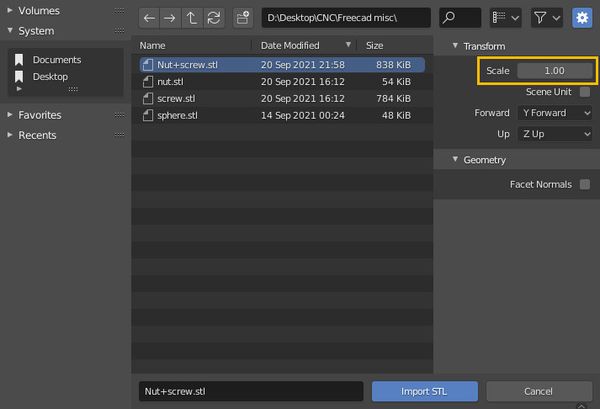
The file picker has a useful option to fix this: scale. If you are designing in mm, you want to set the scale to 1/1000 i.e. 0.001 (but we can always resize our objects later).
When importing a Collada file there is no such issue because the Collada standard explicitly stores what kind of unit it’s using. On the other hand, STL dimensions are generic “units” without any real life reference.
3. Blender basic controls
I have listed below the most useful commands in Blender to manipulate the camera and the objects.
Pressing N will reveal the N-panel, which lists the current size, angle and other properties. We want to enable this so we can easily see and change the dimensions of our items.
| Command | Function |
|---|---|
| Middle mouse button | Rotate the camera |
| Shift + middle mouse button | Pan the camera |
| Left click | Select an object |
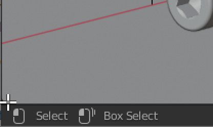
| Left click (drag) | Select multiple objects in an area |
| G | Move the select object(s) |
| R | Rotate the select object(s) |
| S | Scale (resize) the select object(s) |
| X | Delete the select object(s) |
| Shift+D | Duplicate the select object(s) |
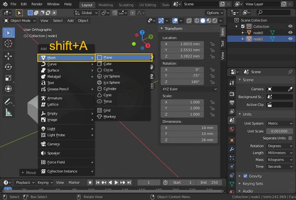
| Shift+A | Add a new object(s) |
| A | Select everything |
| double press A | Deselect everything |
| N | Show/hide panel with object sizes |
| Numpad 0 | Look through the camera |
| Tab | Toggle the mesh editing mode |
| Z | Change the viewport rendering mode |
| F12 | Render |
| Ctrl+S | Save (do it often!) |
4. Create our scene
To to move around our objects, select them with left click and hit G. Then press X, Y or Z to constrain the movement along one axis. Rotation is done the same way with R.
If you want to move an object along two axes only (for example X and Y), after pressing G use shift+Z (or shift + whatever axis you want to exclude). This is useful for moving an object on a flat surface.
If you need to resize an object, press S and move your mouse, then left click to confirm or right click to cancel. If you have the N-panel open, you can enter the new size directly.
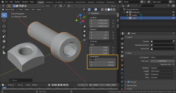
We can resize the selected object by typing any size into the N-panel.
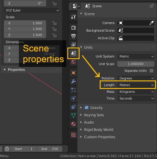
To change the units from meters to millimeters or any other unit, click on the Scene Properties icon and change the Length setting:
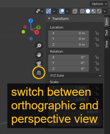
I recommend switching the projection from the default (perspective) to orthographic (Numpad 5). The perspective camera doesn’t work too well with small sizes:
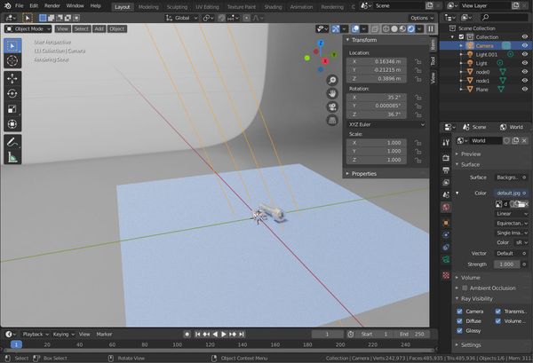
5. Add a background plane
Right now our objects are floating in space. Let’s add a floor with shift+A > Mesh > Plane.
7. Render settings
With our objects placed on a plane, now is a good time to get an idea of what our render will look like.
Press Z and select Rendered to switch from the fast preview mode to a slightly more realistic lighting mode.
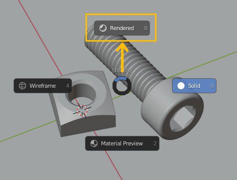
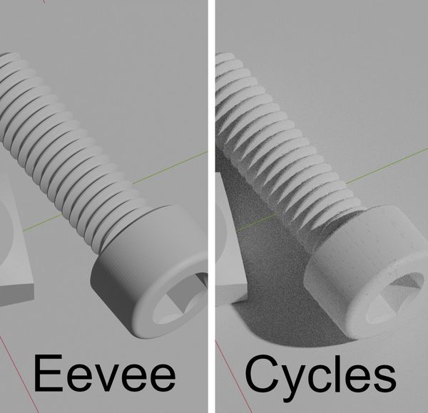
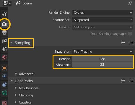
For the Rendered mode we can actually choose between two quality settings, which depend on the render engine we use. The default is Eevee. While it’s fast, we want to use the much higher quality render engine called Cycles.
Cycles can be selected in the Render properties tab (right sidebar, second icon from the top). If you have the option, you’ll want to enable GPU rendering.
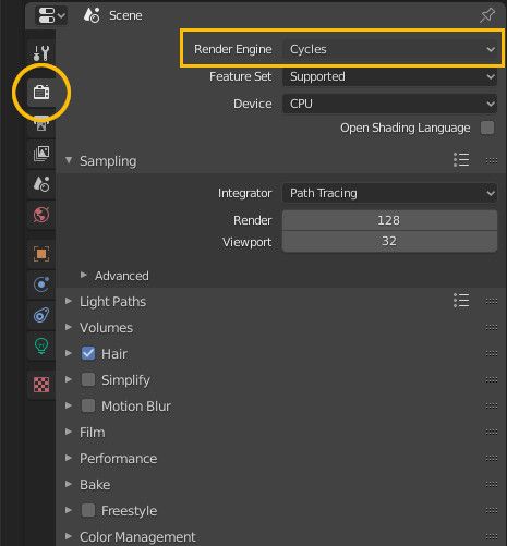
Switching to the Cycles render engine in Render properties.
8. Set up the lights
Now we can see what our render will look like. It’s normal to see some “grain” or visual noise especially in the viewport. Increasing the Samples (Render and Viewport sliders) can improve the quality at the cost of rendering speed.
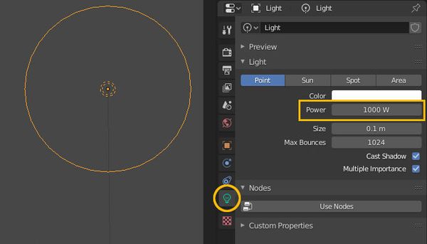
Take some time to move the light around or add additional lights using Ctrl+A > Light > Point (or duplicating the existing one with Ctrl+D).
If you need to adjust the light intensity, select the light(s), and use the Power slider in the Light tab:
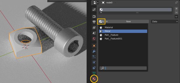
9. Set the materials (and add color)
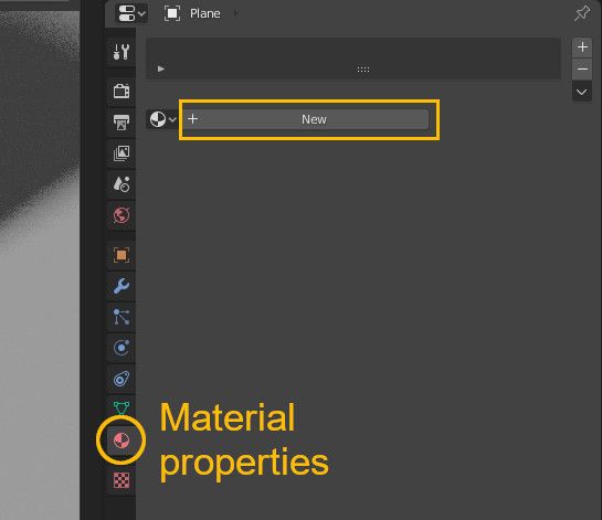
Let’s make our object more realistic by adding a metallic surface and coloring it. Go to the Material Properties tab and add a new material if there is none (if you imported a Collada file, the object may already have one):
Adjust the Metallic and Roughness sliders to make the surface metallic. The roughness slider controls how matte or reflective the surface is. We can also change the color using Base color.
To rename the current material, click on its name.
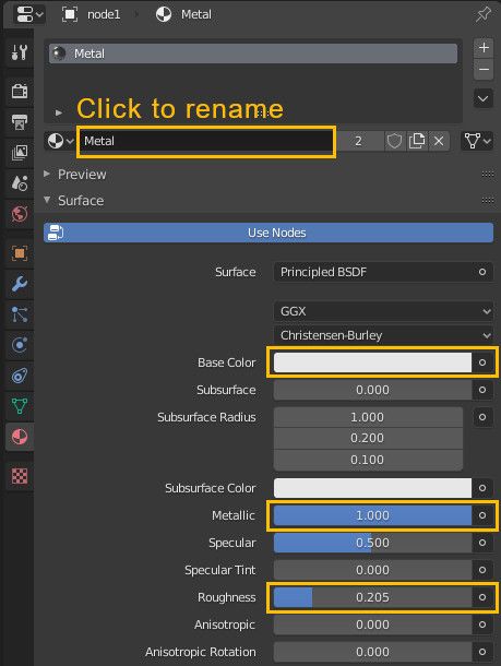
We can easily assign a material to any selected object using the dropdown menu next to the material name. All objects will share the same material, meaning any change to the material will be applied to all objects as well.
10. Place the camera
The last step before rendering is to place the camera and frame our scene. The camera represents the point of view from which Blender will render our picture. To look through the camera, press Numpad 0 or click on the camera icon:
![]()
If you have accidentally deleted your camera, you can add it back with Ctrl+A > Camera.
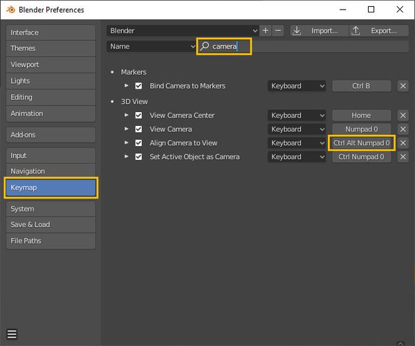
The camera can be moved like any other object with G and rotated with R, but there’s a convenient shortcut that lets us point it exactly where we are looking: Ctrl + Alt + Numpad 0.
If you don’t have a numpad, you can always rebind the shortcut to something else: File > Preferences > Keymap > search for “camera” > click on the shortcut assigned to Align Camera to View and type your new hotkey.
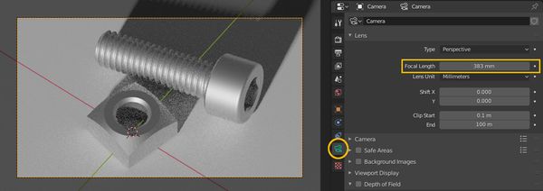
Using this shortcut will cause the camera angle to match the user view. If the camera is too far away, adjust the Focal Length in the Camera tab (or simply move it closer):
11. Render!
We are finally ready to render. But save first (Ctrl+S)! Rendering can take a while and we don’t want to lose our Blender project if something goes awry.
To start rendering, press F12 or click on Render > Render Image. It can take a while…
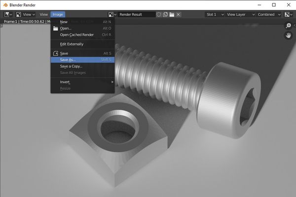
If you’re happy with the result, save the image with Shift+S or Image > Save As….
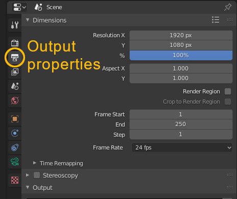
The rendering resolution can be changed in the Output properties tab (by default it’s 1920x1080):
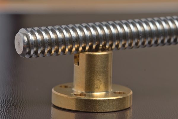
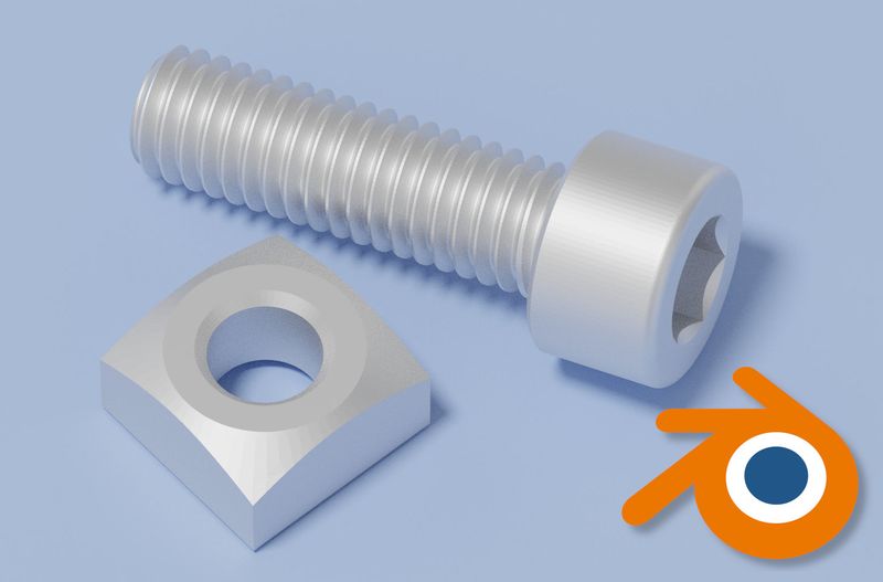
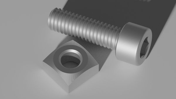
Our final result doesn’t look too bad:
Tips & tricks
How to get smooth curves without visible triangles
One issue with using Blender for rendering is that it’s easy to see the individual faces that form a curve surface. As you can see, the curved head of this bolt is made up of many triangles:
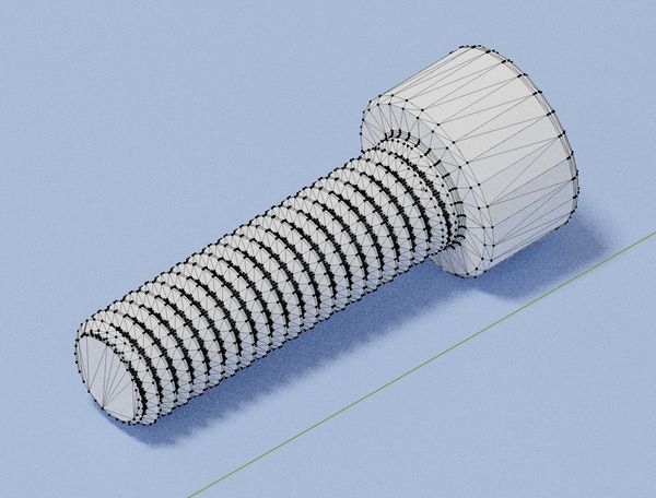
This is an issue with all tessellated formats such as STL, OBJ and Collada (DAE).
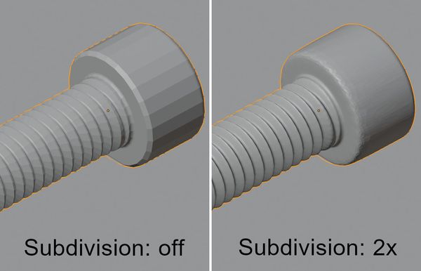
One way to mitigate this issue is to increase the export resolution in Freecad or any other design software. Another option is to use Blender’s subdivision modifier:
- Select the object you want to make smoother
- Click on the Modifier icon (a blue wrench)
- Click on Add Modifier
- Choose Subdivision Surface
- Increase the Subdivisions slider (Render and Viewport)
To toggle the preview in the main viewport, click on the screen icon.
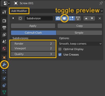
The subdivision modifier has the downside of also rounding the edges that should remain sharp. Because of this, it’s preferable to increase the original resolution of the STL (or any other format) before importing it.
Better lighting with an HDRI environment map
If you’ve read my CADRays tutorial you may be familiar with environment maps. In Blender, they’re usually called HDRI (High Dynamic Range Imaging). An environment map is a texture that is applied to a sphere or skybox around the scene and is used as a light source.
An environment map or HDRI typically emits light from all around the subject, which creates softer shadows and more realistic lighting.
Environment maps can be found for free online (just search for “blender hdri free”) from sites such as hdrmaps.com , ihdri.com and polyhaven.com
I’ll be using the default environment map from CADRays, which can be downloaded from here.
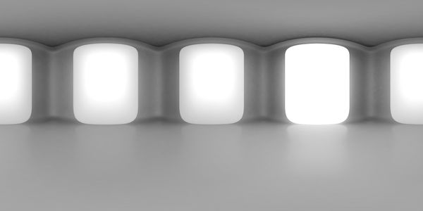
The default CADRays environment map.
Here’s how to add an environment map:
- Click on the World Properties tab icon;
- Click on the white circle next to Color;
- Select Environment Texture;
- Click on Open and select the environment map.
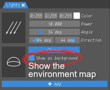
If you are using the Rendered view (press Z to change it) and perspective projection (Numpad 5), the environment map should now be visible in the background:
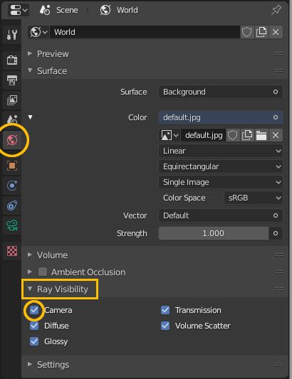
To hide it, uncheck Camera under Ray Visibility:
Here is the final result:
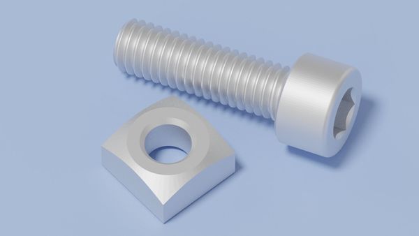
By adding an HDRI environment map and using a single low power light, we get much softer shadows as the light is coming from multiple directions.
Have the camera follow the subject
Placing the camera just right can be annoying. The shortcut Ctrl + Alt + Numpad 0 can is useful to align the camera with the main view, but an even easier method is to tell the camera to track an object. Here’s how to do it:
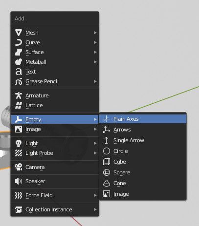
- Press Ctrl+A and add an Empty of any kind:
- Make sure nothing is selected (you can deselect everything by pressing A twice quickly)
- First, select the camera
- Then, select the empty
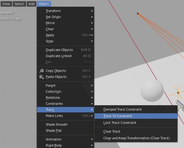
- Click on Object > Track > Track to constraint:
The camera will keep looking at the Empty even as you move the two around. The Empty isn’t rendered and doesn’t affect the lighting, so we can position it wherever we want.
Using multiple panes
It can be useful to see the camera’s point of view and the main view at the same time. This can be done by having two panes open.
At the bottom of the screen you should already have an animation pane, indicated by a clock icon. Click on the icon and select 3D viewport:
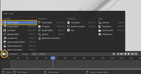
The pane can be resized by dragging the border. We now have two panes: one can be used for the camera in rendering shading mode, and the other for moving items around in a faster shading mode like Solid or Material preview.
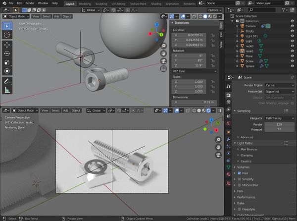
Split panes: the top one is in Solid shading mode, and the bottom one is used as a render preview.
To close a pane, right click on the divider line and click on Join areas.
To create a new pane, hold down the left mouse button and drag one of the rounded corners around the main viewport. The cursor will look like a cross: