
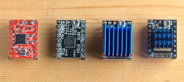
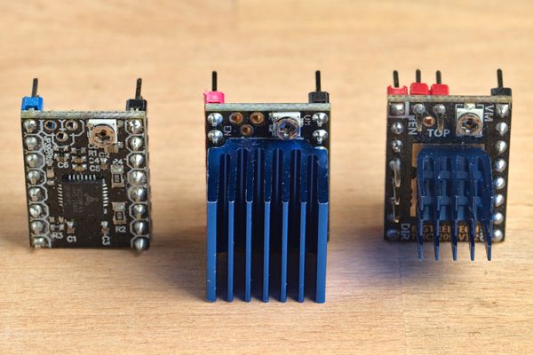
Four popular stepper drivers: A4988, TMC2208 V2.0, TMC2208 V3.0, and TMC2209 V1.2
Why do we need to set the motor/driver current?
First, let’s take a step back and understand our stepper motors and why we even need to set a driver current.
You may be familiar with DC motors. These are extremely simple to wire up: plug them into a DC voltage source (maybe a battery), and they turn. Swap the two wires, and they turn the other way. If we increase the voltage, the motor spins faster.
Stepper motors are more complex. They usually come with four wires, and we can’t even power them directly (unless we want to damage the motor!). Stepper motors have two special requirements:
- We need to limit the current going to the stepper motor coils. This prevents the coils from overheating and possibly melting.
- Most stepper motors use two coils to control the angle of the motor shaft. If we energize the coils in the correct order, the motor’s internal magnet will turn by a set angle (or step) each time. This is why stepper motors are paired with a stepper driver that controls the power going to the motor to precisely turn the shaft with the correct torque.
Every stepper motor has a rated current listed in its datasheet. For example, the Nema 17 stepper 17HS24-1206S has a rated current of 1.2 A. This means we must set its stepper driver to less than 1.2 A, in order to avoid overheating the motor.
Stepper drivers also have their own rated current. For example, the TMC2208 is only rated at 1.2 A without a heatsink.
Additionally, it’s always best to leave some headroom and lower the current by around 10-20%.
What is Vref?
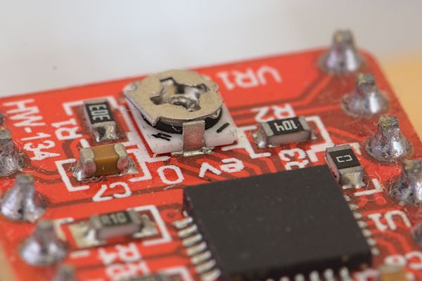
Larger drivers like the TB6600 and DM542 have DIP switches that set the current going to the motor. Small drivers like the A4988, designed to be socketed into a motherboard, instead use a tiny potentiometer. By turning it, we can increase or decrease the current.
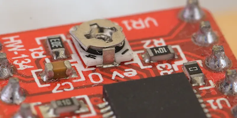
On this A4988 driver, the current-setting potentiometer is located near the motor voltage and enable pins. However, its position can vary from board to board.
This is where the Vref comes in. Vref stands for reference voltage, and is the voltage measured directly on the driver that controls how much current goes to the motor.
- By increasing the Vref, we are telling the driver to supply more current to the motor.
- By decreasing the Vref, we are telling the driver to supply less current to the motor.
To know the current Vref, we have to use a multimeter to measure the voltage between two locations on the board. These are usually the potentiometer itself and a ground pin. We’ll see how to do this later.
To know what Vref we need to set for our desired current, we have to calculate it using a simple formula. This formula depends on what driver we are using.
Vref calculator
 A49880.72 V
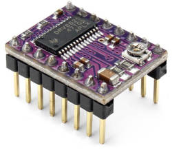 DRV88250.45 V
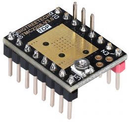 TMC22081.27 V
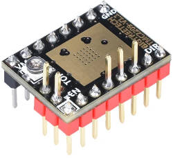 TMC22091.27 V
How to calculate the Vref
A4988
On the A4988 drivers, the Vref is calculated like this:
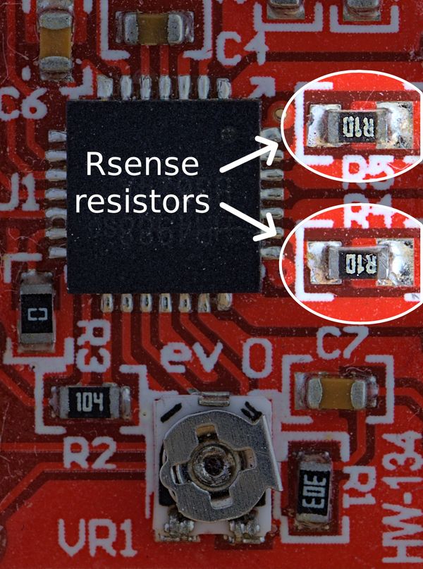
Vref = current * 8 * Rsense
where Rsense is the value in Ohms of the two resistors found on the driver. These are the tiny rectangular components with text printed on them. As different boards use different resistor values, you’ll have to check your individual driver.
I recommend using your phone camera under good lighting to read the text, as it’s very small. You can then look up the value using this online tool.
These are the most common resistor values:
| Resistor code | Value in Ohm |
|---|---|
| R10 | 0.1 Ω |
| R100 | 0.1 Ω |
| R068 | 0.068 Ω |
Let’s say we want our driver to supply 1A of current to its motor:
VREF = 1 * 8 * 0.1
Which means that we’ll have to turn the potentiometer until we measure 0.1 V.
DRV8825
Calculating the Vref for the DRV8825 drivers is easy:
VREF = current / 2
So, to set our driver to 1A, we need to set our Vref to 1/2 = 0.5 V.
Be aware that the DRV8825 has the potentiometer on the opposite side compared to the A4988, so double check the orientation and pinout before wiring or installing it.
TMC2208 and TMC2209
Bigtreetech TMC2208 V2.0, TwoTrees TMC2208 V3.0, Bigtreetech TMC2209 V1.2
VREF = current * 2.5V / 1.77A
or simplified:
VREF = current * 1.41
Wiring guide: how to set the Vref
All driver boards have to be connected to a microcontroller in order to function and provide a Vref reading. The next steps describe two common scenarios: wiring a driver directly to a microcontroller or using an intermediate breakout board.
Bare driver wiring
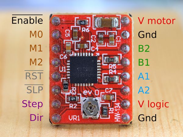
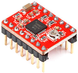
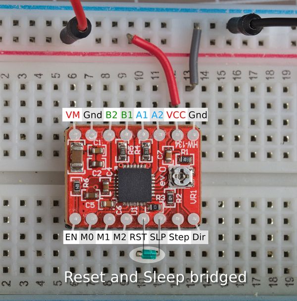
The pins on an A4988. The line above some of the pins indicates an inverted logic: for example, the driver is enabled only when the enable pin is low.
We only need a few wires to hook up our driver to an Arduino or another microcrontroller. The A4988, DRV8825 and TMC2208/9 all work at both 3.3v and 5v, so we can even use 3.3v microcontrollers like an Esp8266, Esp32, or Arduino Zero.
Wiring the A4988
If using an A4988, we need to make these connections:
- Connect the VCC (V logic) pin to 3.3V or 5V
- Connect the Gnd pin to the MCU’s Gnd
- Connect the A4988’s reset (RST) and sleep (SLP) pins together
The driver doesn’t need to be powered through the high voltage (8-35V for the A4988) VM pin, but if you do you should always have a 100uF capacitor across the power supply lines.
Wiring the TMC2208 and TMC2209
I have tested these Trinamic drivers:
- Bigtreetech TMC2208 V2.0
- Twotrees TMC2208 V3.0
- Bigtreetech TMC2209 V1.2
These are wired a bit differently from the A4988, as they require external power from the motor power supply. Here’s how to wire them:
- Connect the VCC (V logic) pin to 3.3V or 5V
- Connect the Gnd pin to the MCU’s Gnd
- Power the driver from the power supply (usually between 9-24V) through the VM and GND pins, using a 100uF capacitor across the two lines.
The capacitor protects the driver from brief high voltage spikes that can occur when plugging in the power supply. Take care to observe the right polarity when using electrolytic capacitors: a white strip or a minus sign typically marks the negative lead (which is shorter than the positive lead).
Without the power supply plugged in, I observed low Vref values (between 0-0.2V) no matter how I turned the potentiometer.
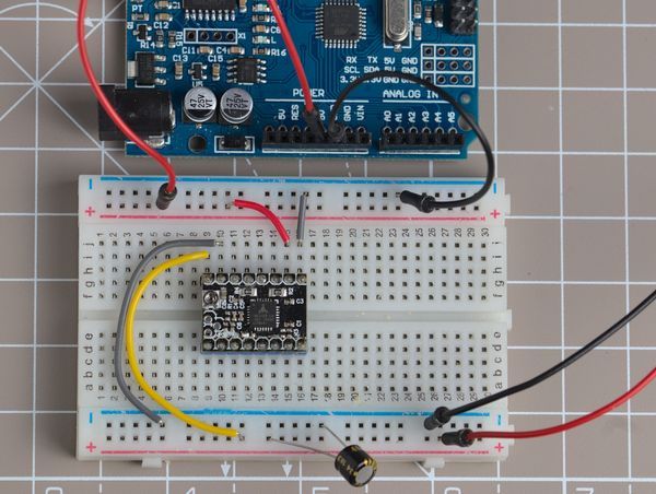
Wiring the TMC2208/TMC2209 to set the Vref requires powering it with 5-36V through the VM and Gnd pins. Notice the 100uF capacitor across the power supply lines.
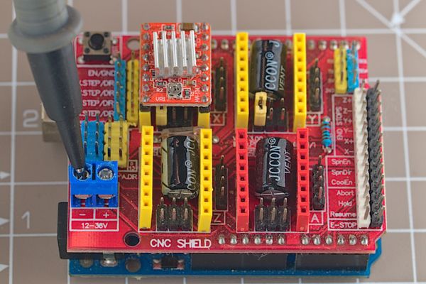
CNC shield and other breakout boards
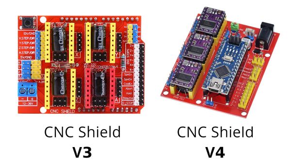
There are two CNC shields around: V3 is designed for the Arduino Uno, while V4 fits an Arduino Nano. They come with 100uF capacitors, jumpers to set the microstepping mode, and many pins to wire limit switches, an emergency stop and a spindle.
These CNC shields make it trivial to connect a driver to a microcontroller and motor, as there is no additional wiring needed: just plug the driver into the socket, and connect the shield to the microcontroller.
We don’t have to worry about bridging the A4988’s Reset and Sleep pins, as the CNC shields already do it for us.
Note that if you are using the TMC2208 or TMC2209 you’ll need to connect a power supply to set the Vref.
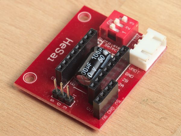
In addition to the CNC shields, there are various other boards that make it easy to hook up a driver to a microcontroller and motor. Using these is generally the same as using a CNC shield.
Always double check the orientation of your stepper driver. The position of the potentiometer is not necessarily the same between different boards, so you shouldn’t use it as a reference point. Instead you should look for the EN (enable) pin marking that is usually printed on your CNC shield, 3D printer motherboard, or other board, and you should use that as a reference.
Setting the Vref
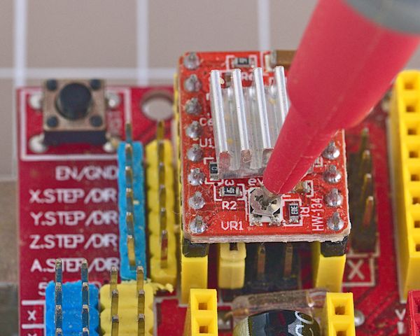
To summarize, in order to set the motor current we will have to turn the potentiometer on the driver and measure the Vref until we read the correct value.
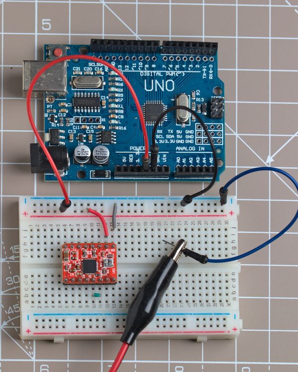
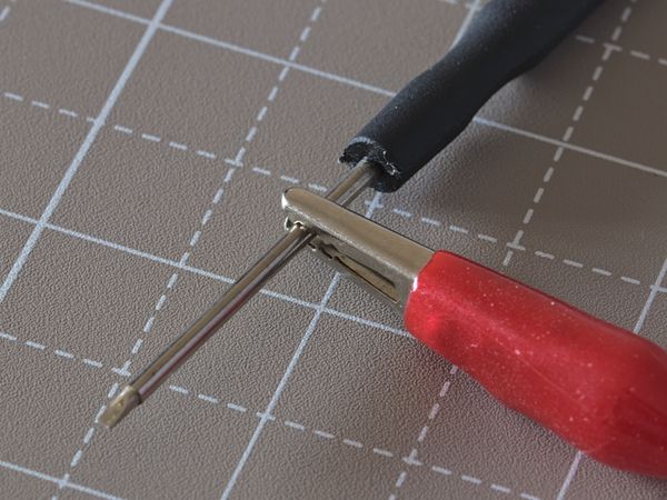
For this, we’ll need a multimeter and a small screwdriver. I’ll also be using an alligator clip to hook up the multimeter to the screwdriver in order to get a real time reading of the Vref.
I’ll be using a metal screwdriver with an alligator clip, but be aware that there is a risk of accidentally shorting parts of the driver and irreversibly damaging it. For this reason, it’s sometimes recommended to use a ceramic screwdriver (or any other non-conductive kind).
Wire the driver to your microcontroller as described above.
Plug in the microcontroller, as the driver must be powered through its logic pin. Leave the motor disconnected.
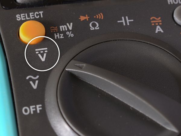
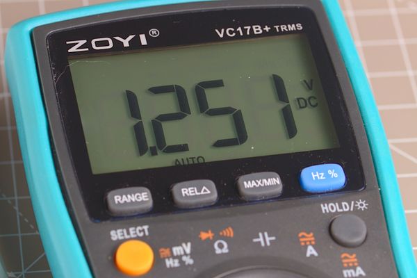
Set your multimeter to DC voltage mode, which is indicated by a V with a dashed line and a straight line on top:
If you are using a metal screwdriver, use an alligator clip to attach one multimeter probe to the screwdriver (otherwise skip this step).
Touch a ground point with the other multimeter probe. The CNC shield v3/v4 and other driver breakout boards usually have a screw terminal for the power supply’s Ground which we can use.
If the driver is on a breadboard or directly wired to the microcontroller, attach the multimeter probe to the ground rail or MCU ground pin.
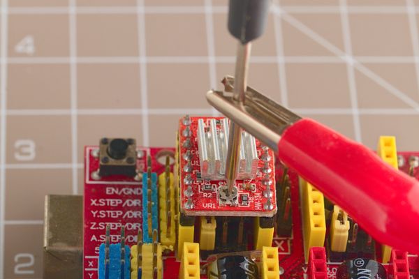
Touch the potentiometer with the multimeter probe or with the screwdriver if it’s connected to the multimeter.
Read the voltage on the multimeter: it should be between 0 and 1.2V or 0-1.77V depending on the driver.
Turn the potentiometer until the voltage is right. Usually, turning it clockwise will increase the voltage. Watch out: some pots have a small metal tab that marks the end of the travel. This tiny tab can easily break if you turn the pot too far. Turn it very slowly and carefully.
Driver datasheets
For reference, below are links to the datasheets of the drivers discussed in this tutorial. They are useful if you need information like voltage ratings, microstep settings, and details on the pinout.