3D printers, CNC routers, and other CNC machines are capable of incredible accuracy, but only if set up right. When we tell our machine to move 50mm (2”) along X, we want it to move that exact distance every time. Do do so, we have to calculate the steps per millimeter.
Steps per mm calculator
Steps per mm explained: lead screw
This is the formula to calculate steps/mm for a lead screw:
An example
Let’s say that our motor steps 200 times per full turn. We configure the microstepping ratio to be 1/8th (8 microsteps for each full step). The screw we are using has a lead of 2mm (more on this below).
If we run this simple math, we get 800 steps per mm.
What is the lead in a lead screw?
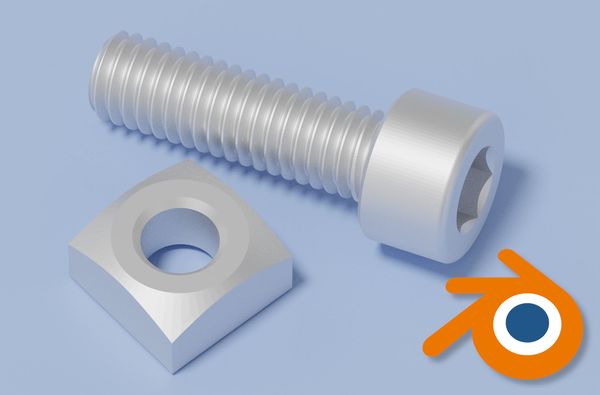
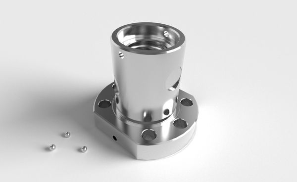
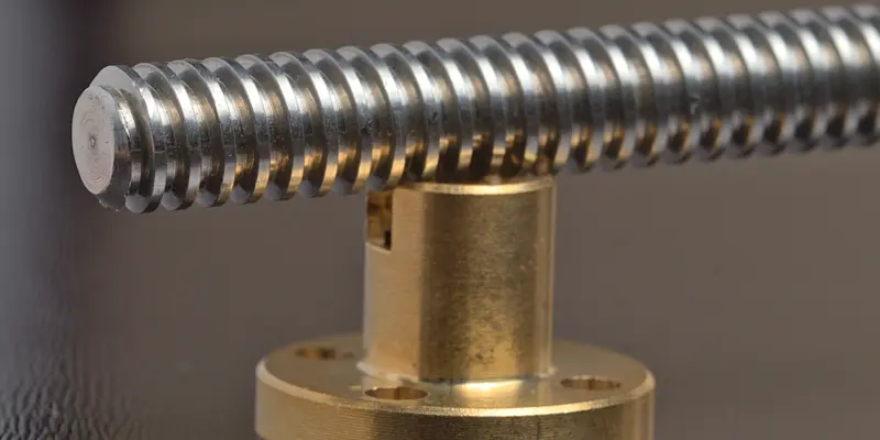
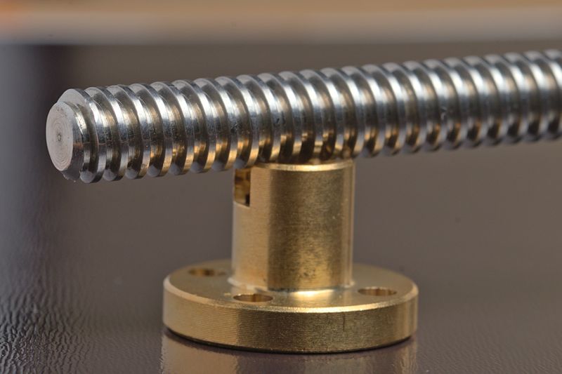
A lead screw with 2mm pitch and a compatible nut
A screw’s lead is the distance a nut moves per full revolution of the screw. For example, a screw with a lead of 2 mm will move a nut by 2 mm for each full turn.
A screw’s lead is often different from the pitch. The pitch is the distance between two adjacent teeth. On some screws, the lead and pitch are the same: these are single start screws. A single-start screw has only one helical tooth running through it.
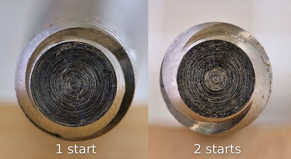
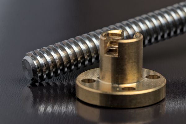
You can tell how many starts a lead screw has by looking at its profile.
On a multi-start screw, the pitch and lead are different: for example, a two-start screw with a pitch of 2 mm will have a lead of 4 mm (2*2).
Most lead screws have a pitch of 2 mm and between 1 and 4 starts. Therefore, they have a lead between 2 and 8 mm.
| Pitch | Starts | Travel per full revolution (lead) |
|---|---|---|
| 2 mm | 1 | 2 mm |
| 2 mm | 2 | 4 mm |
| 2 mm | 4 | 8 mm |
Keep in mind that a lead screw requires a nut that matches both its pitch and lead.
Steps per mm explained: GT2 timing belt
This is the formula to calculate steps/mm for a GT2 timing belt:
An example
Let’s say that our motor steps 200 times per full turn. We configure the microstepping ratio to be 1/8th (8 microsteps for each full step).
We are using a GT2 belt, which has a distance between teeth of 2mm. We attach a pulley with 20 teeth to our stepper motor.
If we run the math, we get 40 steps per mm.
What is the pitch in a timing belt?
Belts are a popular choices when high feed rates and accelerations are desired. 3D printers, pick and place machines and pen plotters frequently use belts. The de facto type of belts in the hobby space is the GT2 belt (also known as 2GT).
Belt pitch is the distance between teeth. More precisely, it’s the distance between the same feature on adjacent teeth, not the size of the gap between them:
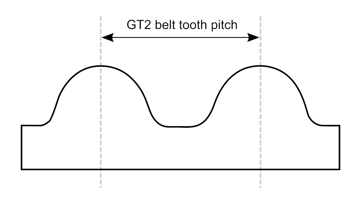
GT2 belts
GT2 belts typically have a tooth pitch of 2 mm (but not always: the “2” in GT2 does not indicate the pitch).
The other parameter we need is the number of tooth in the pulley. Common values in 3D printing and small CNC machines are 16 or 20 teeth (16t / 20t).
By multiplying the belt pitch and the pulley teeth count, we know how far the gantry moves for one full turn of the stepper motor. If we use a 20t pulley with a 2 mm belt, each turn of the motor results in 40 mm of movement.
How to configure steps per mm
Now let’s see how to save the values we calculated to the machine firmware.
Marlin
If your 3D printer runs Marlin, settings the steps/mm is simple even if the display doesn’t allow it:
Connect your printer via USB
Install Pronterface, which is an awesome tool to control your 3D printer from any PC
Select the right port and connect to your 3D printer
Send the appropriate G-code:
Command Usage G92 X* Set * steps/mm for the X axis G92 Y* Set * steps/mm for the Y axis G92 Z* Set * steps/mm for the Z axis For example, sending
G92 X100 Y100will set both the X and Y axes to 100 steps/mm.Send the
M500command if you want to save these settings to EEPROM. If you don’t, they will be reset to the previous values when the printer shuts down.
We can also get the current steps per unit with the M503 command.
If you are compiling Marlin, the steps per unit can be set inside Marlin/Configuration.h (ctrl+F for DEFAULT_AXIS_STEPS_PER_UNIT):
/**
 * Default Axis Steps Per Unit (steps/mm)
 * Override with M92
 *                                      X, Y, Z, E0 [, E1[, E2...]]
 */
#define DEFAULT_AXIS_STEPS_PER_UNIT   { 160, 160, 80, 80 }
Grbl
Many hobby CNC machines run Grbl: for example the 3018 Pro, Shapeoko, X-Carve, and OpenBuild’s BlackBox controller. Here’s how to set the steps/mm:
Connect the machine to a computer via USB.
Open a G-code sender such as UGS, bCNC, Candle or CNC.js, and connect it to the controller.
Use the serial console to set
$100=N,$101=N, and$102=N, whereNis the steps per mm we calculated:Command Usage $100=N Set the X steps/mm to N mm $101=N Set the Y steps/mm to N mm $102=N Set the Z steps/mm to N mm The full list of Grbl settings is available here.
If you want to know the current values, send the command $$ to view all the Grbl settings. Here’s a tip: if you use UGS or CNC.js, you’ll see descriptions for each setting which otherwise are missing with Grbl v1.1 (due to the limited hardware on the Arduino Uno).
Tip: calibrating steps/mm with a ruler
The calculations we have seen provide a good baseline to set up a machine. However, sometimes the accuracy is still slightly off. This is due to mechanical inaccuracies: maybe the stepper motor turns by 1.805° per step instead of 1.8°, or the belts are slightly off spec.
Fortunately, these problems can be fixed in software very easily:
- Grab a ruler (or some other object of known length), ideally as long as the travel of the axis.
- Set it on the bed of the machine, parallel to the axis.
- Position the gantry or toolhead so that it is almost touching the ruler. Take note of the physical location.
- Jog the machine by the length of the ruler, so that it reaches the other edge.
- Since the ruler tells us how far the machine has actually jogged, we can calculate the error. For example, if we told the machine to jog 100 mm but it travelled 100.5 mm, the error is 100.5 / 100 = 1.005 or 0.5%.
- Now we just have to adjust the steps/mm using this error ratio. In our example, we divide the value by 1.005. This gets us 100 / 1.005 = 99.5. If the machine had travelled 99.5 mm, the error would be 0.995 (99.5/100), so our new steps/mm would be 100/0.995 = 100.5.
- Save the new settings and we’re done!