Freecad is an incredibly useful and free open source tool to make 3D models, and making a 3D render can be a great way to view the result before manufacturing or sharing.
CADRays is probably the easiest way to quickly render a 3D model. It’s based on Open Cascade , a free and open source 3D modeling library that Freecad itself uses in order to calculate how to create and combine surfaces.
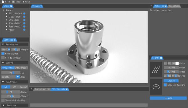
CADRays, a 3D renderer
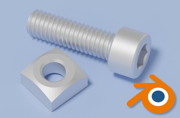
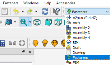
For this tutorial, I’ll be rendering a set of screw and nut made with Freecad’s Fasteners workbench. If you don’t have it, you can enable it from Tools > Addon manager > Install/update selected. Then switch to the Fasteners workbench and add the screws with Fasteners > Add Fasteners.
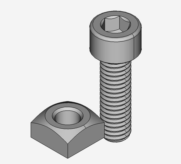
Our model in Freecad
1. Downloading CADRays
Download CADRays from this page (sign-up required). It’s a portable install, so just unzip it anywhere and run CADRays.exe inside.
Unfortunately there are no available binaries for Linux or Mac OS, and it doesn’t look like they’re in development either. I have not tested CADRays under Wine on Linux.
2. Importing our step file
CADRays can import our model as a step (STP) file. To export a Freecad project as a step file, select all the parts or bodies that you want to export, and click on File > Export selecting STEP with colors (.step, .stp) as the file type.
Import our step file into CADRays using File > Import.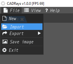
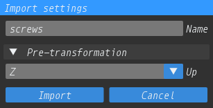
We can import multiple step files into the same scene, and we can import the same file many times to duplicate it (unfortunately there is no real clone feature).
The import dialog will asks the name for the object (we can’t change it later!) and which way is up. No need to worry about the orientation for now, as we can rotate everything later. For models exported from Freecad, the default Z Up will work fine.
Our imported object(s) will be listed in the Scene tab, where they can be selected by left clicking on the name and hidden/revealed by clicking on the blue dot.
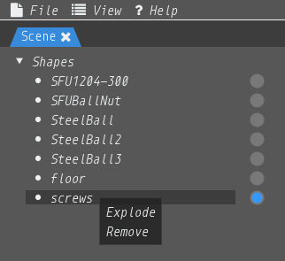
If the step file we imported is made up of multiple parts, we can access them by right clicking on the name and then on Explode.
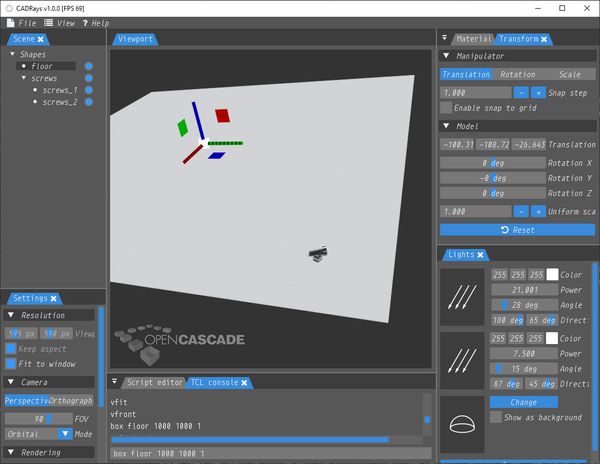
3. CadRays camera controls and settings
Let’s get an idea of how to look around inside CADRays:
- Hold the middle click to pan the camera
- Hold right click to orbit the camera
- Scroll the mouse wheel to zoom in/out
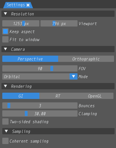
In the settings, we can pick the export resolution (deselect Fit to window to enable resolutions higher than the viewport) and the projection type between perspective and orthographic.
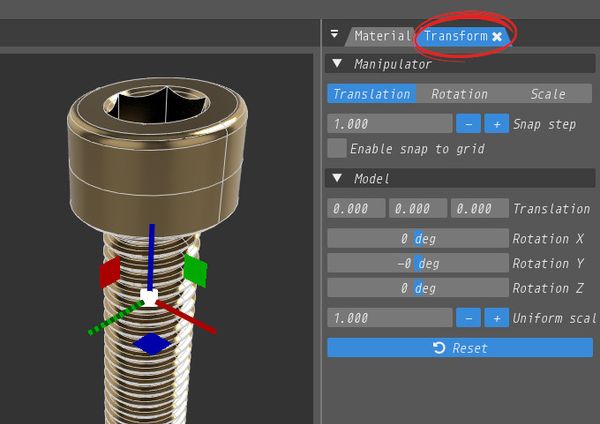
4. Moving and rotating objects
With our objects selected, we can move/rotate/scale them in the Transform tab, using the sliders or the handles overlaid on the object.
To type a value directly into a field, use CTRL + left click.
5. Setting materials
Our screws have an odd gold color by default. Since they’re supposed to be steel, let’s change this using the Material tab.
Select the object we want to change, and pick the material type for ray-tracing (BSDF, or bidirectional scattering distribution function) and its color (right click on the color box).
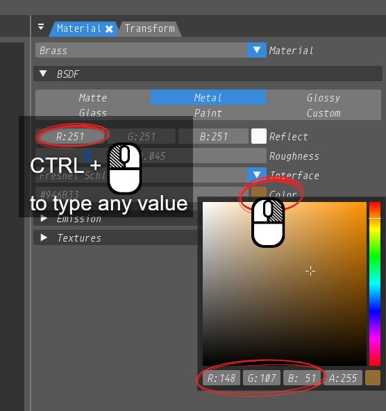
Right click on a color box to open up the color picker
We can also add a texture, which shows best with the matte material.
6. The TCL console
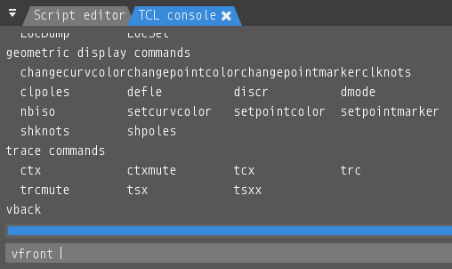
In the lower part of the screen we can see the TCL console, which is a way to modify the scene by typing text commands (using the TCL programming language). We can use it to control the camera, background, and create new objects.
For example, if we type vfront and hit enter, the camera will be positioned to view the selected objects from the front.
Here are some useful commands:
Hitting up arrow will load the last used command.
7. Setting the background
Sometimes we want a different background than the default solid gray. We have a few choices:
- Set a different solid background color
- Set an environment map (more on this later)
Changing the background color is done with the vsetcolorbg command from the TCL console:
vsetcolorbg 255 255 255
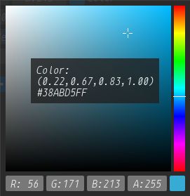
This sets the background color to white. The color is in RGB format, where each number indicates the brightness of the red, green and blue channels between 0 (black) and 255 (white).
We can use any color picker inside CADRays to get the RGB values for a color:
8. The environment map
The environment map is a texture that appears as a 3D sphere (skybox) around the scene and also influences the lighting. It’s shown in the Lights tab, where we can use it as a background:
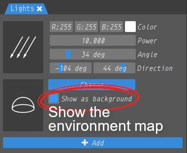
Keep in mind that even when hidden it still emits light. The default environment map has four lightboxes:
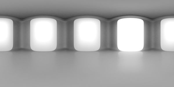
The default environment map in CADRays
It’s very easy to set our own environment map. Just search online for “free equirectangular images” or “free skybox texture”. We want the images with a 2:1 aspect ratio, not the cubemaps.
We can even use any 360° photo like these available on Flickr.
If you want to restore the CADRays’ default environment map, you can load it from the install folder: CADRays-1.0.0\data\maps\default.jpg.
Also keep in mind that the camera must be set to perspective for the environment map to show properly as a background.
9. Adding a floor, backdrop or other object
If the scene we imported didn’t have a floor, we can add it and texture it right inside CADRays.
For this we’ll use the TCL console. The following command will add a box named “floor” with dimensions of 1000 x 1000 x 1 (you can pick any name you want):
box floor 1000 1000 1
By default, our object is hidden. We can show it with vdisplay followed by the object name:
vdisplay floor
Then we can select it in the Scene tab, move it and change the material however we want.
Adding a floor to our scene with the box command.
10. Set the lights
If you orbit the camera around, you’ll see the default light source as a big white circle in the sky. This can be adjusted with a few sliders:
- Power obviously changes the strength of the light source
- Angle actually changes the size of the light source, which affects how soft or harsh the shadows look. You’ll want to decrease the power as you increase the angle.
- Direction rotates the light source around the horizon (horizontally) or across the sky (vertically).
The default light is Directional, meaning it acts like the Sun. We can also add a Positional light, which works like a lamp and can be moved around the scene.
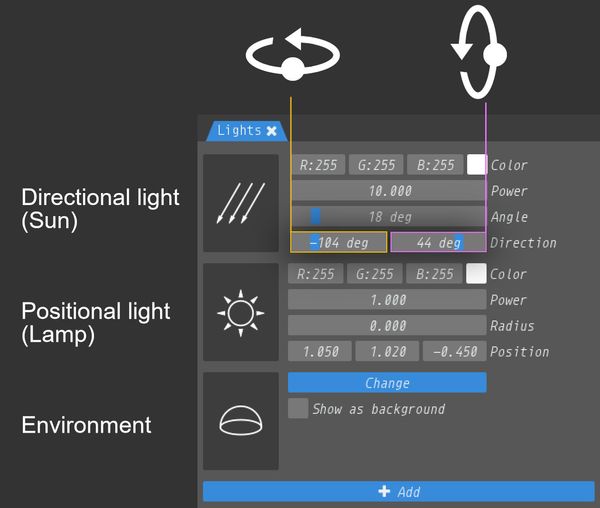
The directional light direction anlges control the position of the light in the sky.
11. Export the image
We are now ready to render our image with File > Save image.
To increase the ray tracing quality, try increasing the Bounces and also the Clamping to reduce any noise.
Since CADRays actually saves exactly what’s rendered in the viewport, it may take a few seconds for the noise to clear up, so wait a few seconds from the last change before saving the image.

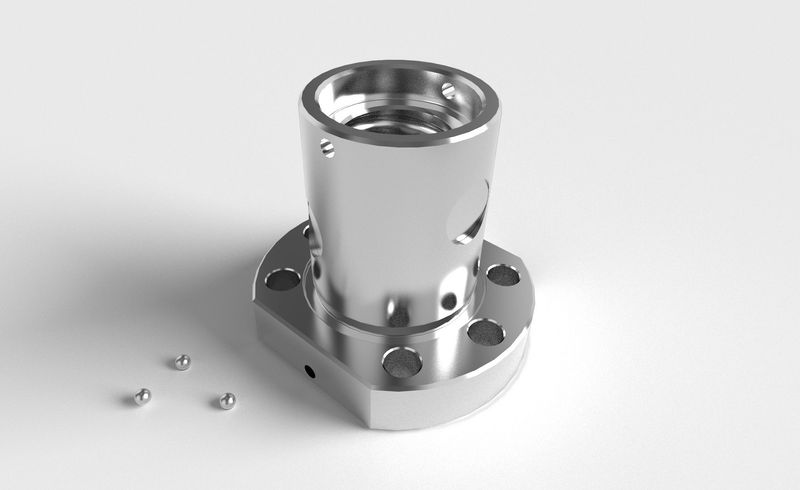
The final result