If you just purchased your first CNC router, you may be looking for a free program to start generating your own G-code and get your first cuts going. One great choice for beginners is Carbide Create, a free CAM software that works with most hobby CNC machines and is very simple to use.
What exactly is Carbide Create?
Carbide Create is both a design tool and a G-code generating tool: we can create our own shapes and designs on our virtual stock of material, select a virtual end mill, and create a toolpath that our CNC machine will follow when running the exported G-code.
The design process is known as CAD (computer-assisted design), while the CNC-related steps are known as CAM (computer-assisted manufacturing).
CAM programs make it possible to use CNC machines without writing a single line of G-code by hand, and allow very complex cuts to be programmed easily and reliably.
What is a CAM program?
A CAM program (standing for computer-aided manufacturning) is a program that is used to turn an image or 3D model into a list of commands (G-code) that a CNC machine will execute.
Basically, it’s what lets us turn this…
Using Carbide Create to cut a rectangle
…into this G-code file, which our CNC router will run:
%
(TOOL/MILL,0.1,0.05,0.000,0)
(FILENAME: )
()
G21
G90
G0X0.000Y0.000Z3.000
(TOOL/MILL,3.1750,0,1.0000,0.0)
M6 T20
M3 S18750
G0X7.588Y7.588
G0Z3.000

(...)

G0Z3.000
G0Z3.000
M5
M30
(END)
2.5D vs 3D CAD
Let’s talk about the difference between 2.5D CAD and 3D CAD.
Most CNC routers are 3D machines, meaning the tool moves along three axes. Indeed, all CAM programs output G-code controlling all three axes in order to perform a cut.
However, the difference between 2.5D CAD and 3D CAD is in the simultaneous use of all three axes to follow a 3D surface.
On the other hand, if a cut follows a 2D path that is simply shifted along the Z axis, then it’s known as 2.5D milling.
Using a CAM program
Using a CAM program typically involves multiple steps:
- Designing the 2D or 3D object, or importing it from another program.
- Choosing the parameters that the machine will use. This includes setting the right speed for the axes and the spindle, setting the cutting depths, and choosing the order of operations.
- Saving the G-code file (it usually has an .nc extension) and using a G-code sender to have our machine execute its commands.
We’ll see how to accomplish all of this in this tutorial.
What CNC machines does Carbide Create work with? What is the difference between V6 and V7?
Carbide Create is made by Carbide 3D for their desktop CNC machines such as the Shapeoko series and Nomad.
At the time of writing, the latest version of Carbide Create is version 7 . However, unlike with the previous versions, it is not possible to export G-code files anymore. As a result, CC V7 cannot be used with most CNC machines (e.g. a Sainsmart 3018, X-Carve, etc).
In order to actually send the G-code to a CNC, V7 users must instead use Carbide Motion , which only works with Carbide3D’s own Shapeoko and Nomad series of CNCs. You can read more about the reasons behind this change here.
If you have a Shapeoko/Nomad machine, you can get V7 here.
Otherwise, Carbide Create V6 can still be downloaded from the official Carbide3D website.
This guide applies to both versions.
Design (CAD)
1. Job setup and grid
The job settings has a few options that are very important yet easy to overlook.
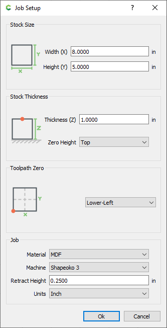
The stock size is purely a visual setting, and doesn’t have to match your machine’s working area.
The zero height setting will depend on how your machine probes the surface. Chances are you’ll use a piece of paper or a removable touch plate to set the zero position on top of the stock, in which case you’ll want to choose top. This is what you’ll typically want to use.
Zeroing the Z axis on the bottom of the stock is useful when milling down a piece of stock to a desired height (facing), if the material surface is uneven.
The toolpath zero position represents your machine’s zero position along both X and Y axes. I almost always use a corner rather than the center, as it’s easier to locate the edge of the cut near the edge of the stock to minimize wasted material.
Retract height is how far the toolhead will rise above the material surface when not cutting (i.e. during rapid moves).
You should make sure that this value is greater than the height of any clamps you are using, unless you’re absolutely sure that the tool will not collide with them. Tip: keep in mind that if you start your G-code when the tool is not on the zero position, it may still hit a clamp on its way there… at rapid speed (speaking from experience).
Lowering the retract height can be a huge time saver, especially if you are cutting many non-continuous paths. This is because the Z axis typically moves very slowly.
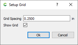
The grid is extremely useful because shapes automatically snap to it. You should design your part to take advantage of this: if you need a bracket with two holes 3/8” apart, set the grid to this value. You can always change the grid size later, and this spacing will remain.
Grid snapping can be toggled from View > Snap to Grid.
2. Creating shapes (vectors)
With the design tools, we can create a number of tools to create and modify shapes, most of which are self explanatory. I’ll share a few tips:
Shapes snap (automatically align) to other shapes when moved next to a corner or other feature. This makes it easy to set the right spacing between shapes by snapping them to another shape that won’t actually be cut:
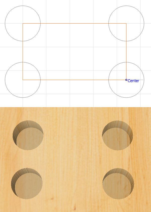
Snapping features to a vector used only for alignment makes it easy to set the correct spacing.
When you create a curve, hold down the left mouse button to set the curvature between two segments. This can be later changed by selecting the shape and clicking on the Node Edit icon. You’ll see movable handles around each point that set the curvature:
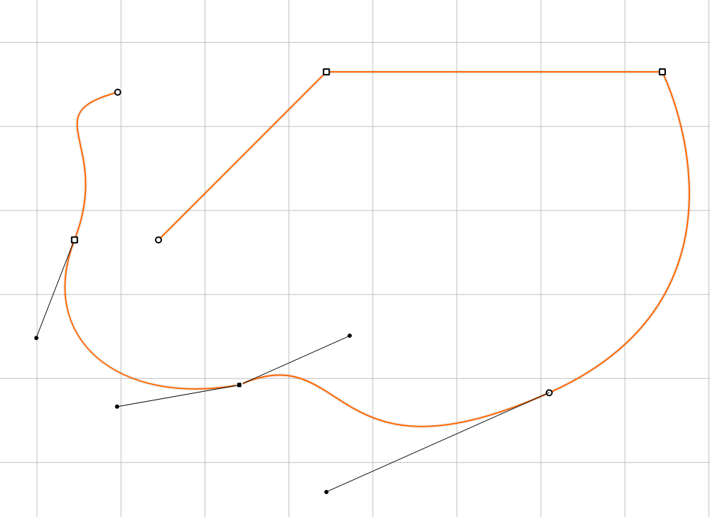
Carbide Create uses Bezier curves.
The circle tool can be used to create ovals. Place a circle, select it, and then click on the Node Edit icon. You’ll be able to click on each point of the Bezier curve and move it to creat and oval or other shapes. You can also add new nodes by right clicking on the line.
Squares and rectangles have a useful fillet and chamfer option. However, the fillet/chamfer is always applied to all four corners. The Node Edit tool can be used to remove a fillet/chamfer from any corner (click on a node an press D), although you lose the the ability to set the radius of the remaining fillets/chamfers as a parameter. Another option to remove fillets/chamfers is to use the Boolean difference tool.
The node edit tool can also be used to remove fillets
You can flip shapes horizontally or vertically. This works for multiple shapes as well, so if you’re making a symmetrical part it’s faster to draw one half, copy it (Ctrl+C), select all shapes, and flip it.
The Align Vectors tool is incredibly useful: if one shape is selected, it is centered within the stock along one or more axes; if multiples shapes are selected, they will be aligned along the X axis, Y axis, or both (centered). The first shape selected will be aligned with the last selected (marked by a dotted border).
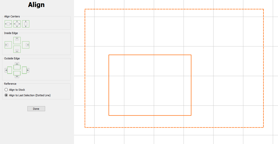
The Align Vectors tool makes it easy to center a shape inside another shape, or align them along X or Y.
3. Importing images: SVG and raster (bitmap)
Carbide Create’s design tools are useful, but you may never actually use them. We can instead import shapes in vector format and even raster images:
We can import an SVG/DXF (left) vector image or a regular JPG/PNG (right)
- Vector formats like SVG and DXF are actually text files that describe how to draw shapes. These can be directly imported and exported using Carbide Create and any other 2D CAM program or vector drawing program like Inkscape.
- Raster images like JPG and PNG are different: they are made up of a grid of pixels. Our CNC machine cuts lines, not pixels, so we have to run the image through a process that detects the outlines and turns them into vectors. This is known as vectorization or simply image tracing. Carbide Create comes with its own tracing tool, which works similarly to Inkscape’s Path > Trace Bitmap tool.
Here’s a tip:
Before tracing a raster image with Carbide Create or Inkscape, you may want to edit it with a separate program like Photoshop or Gimp, using editing tools like Levels and Curves, to get a well defined outline. I like to use the channel mixer to control the lightness of each color, and the median blur filter to remove speckles.
Cleaning the input image is way easier than editing the vectors afterwards!
Setting up the toolpaths (CAM)
Here is the meat and potatoes of Carbide Create: creating toolpaths for our machine. Carbide Create will calculate the path that the machine tool will follow in order to perform the cuts we want: contours, pockets, slots and more.
4. Add and manage CNC bits
When we ask Carbide Create to calculate a path, it needs to know the size of our tool: if we want to completely mill out (pocket) a hole, a small tool will require a much longer path.
We can set our tool library from Edit > Show tool database. Carbide Create already comes with a lot of presets for separate materials:
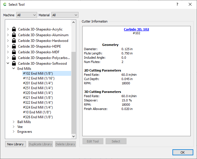
Carbide Create has presets for straight end mills, ball-nose end mills, and V-bits.
(If all the sizes and bit types match the tools you own, then feel free to skip to the next section, where we use them to create toolpaths!)
The reason each tool library is associated with a type of material (acrylic, softwood, etc) is because each tool may need different feedrate: if you cut acrylic too slow, it may melt from the heat caused by friction; if you cut metal too fast, the tool may break. Getting the feedrate and spindle speed just right can require a lot of experience and testing.
You’ll notice the libraries reference the Shapeoko and Nomad CNC routers, but this doesn’t mean we have to use those machines.
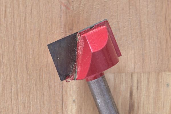
Anyway, we want to be able to add our own tools. Let’s say we have we have this nice set of surfacing bits we want to use to level our spoilboard. They have a shank size of 1/4”. Let’s add the tool with a cutting diameter of 1” (25.4mm).
- We can’t modify the existing libraries and tools in any way, so we’ll need our own library: click on New Library.
- Pick a material type and library name. The machine type doesn’t actually matter.
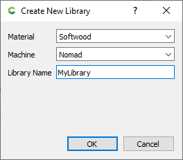
Adding a custom library of tools
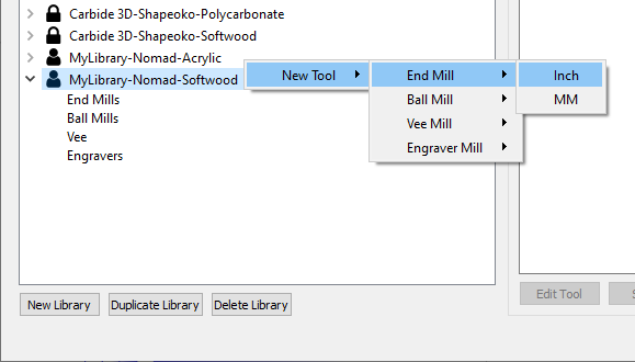
- Add a new tool by right clicking on the library name. End mill indicates a straight cutting edge, which is what we want:
- Let’s choose a name and default 2D plunge rate, feedrate, spindle RPM, and depth of cut (i.e. the maximum depth of each cutting pass). Keep in mind that these are only defaults, and each toolpath we make can use different settings. The 3D settings are only used in the paid Pro version, and we’ll skip these for now.
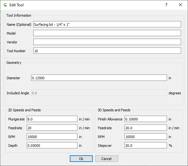
With our tool ready, we can make toolpaths!
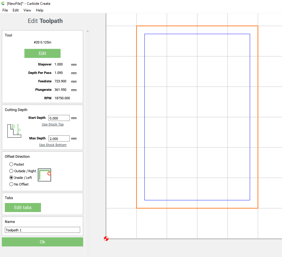
5. Create toolpaths
Carbide Create lets us define a number of types of cuts. In order to create a toolpath, we need one or more vectors selected first:
- Contour: this is a cut that follows a line, either with the tool center along that line (No offset), or with the tool edge following the line (Outside or Inside offset). When making a part, the contour is usually the last operation performed.
- Pocket: a pocket operation is designed to mill out an area of stock entirely, not just the contour, down to a set depth.
- Texture: this works similarly to a pocket, but is used with non-straight bits (ball-nose and v-bits) to create a scalloped profile. The stepover variation % varies a more natural look by avoid a constant width between cuts.
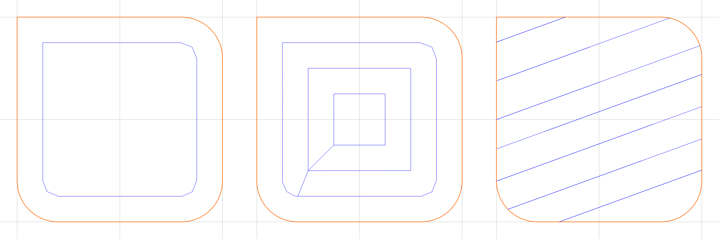
Toolpaths compared: inside contour, pocket, and texture
Drill: a drill operation only moves the tool vertically along Z. It’s usually recommended to use the Peck option or even Full retract so that the tool repeatedly retracts between plunges in order to let the chips exit the hole.
Be careful! Many end mills are not designed to be plunged straight into the material. Only upcut bits should be used. If you cut with a straight-flute bit or a downcut bit, the material is not pushed up and out of the hole. This can cause the bit to overheat and, if cutting wood, possibly start a fire!
VCarve & Advanced VCarve: V-carving uses pointed end mills called V-bits, which can achieve incredible results by cutting extremely fine grooves. More on this later.
Order of operations
As we create toolpaths, they will be listed to the left. Remember that the order matters! The machine will run operations from top to bottom.
For example, you’ll always want to cut a contour after cutting the inside features. If you cut the features first, the part may break off even if you are using tabs (more on this later). You can change the operation order by dragging them.
6. Adding tabs to a contour toolpath
Very often the last operation in a job is to cut out the contour of the path to remove the milled part from the stock. However, unless you are using double-sided tape or a vacuum table, when your machine is almost done cutting the contour, the part may suddenly break off on its own and possibly hitting the tool. This results in damage to the part.
To avoid this, we use tabs. These are small “bridges” that connect the part to the surrounding stock, keeping it in place, and are manually removed later.
In V6, tabs can be added when creating or modifying a contour toolpath.
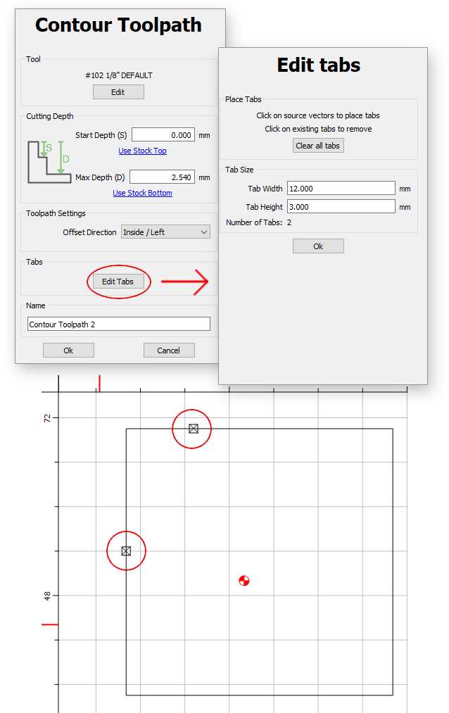
How to add tabs to a contour in CC V6
In V7, tabs are added from the Design tab > Edit section: “Edit Tabs”
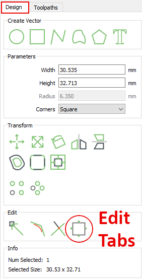
How to add tabs to a contour in CC V7
While in the edit tab menu, left click on any spot on the line where you’d like to add a tab. Left click again on a tab to remove it.
7. Simulate the cut in 3D
Carbide Create has a great 3D simulation tool that displays the final cut. This is very useful to make sure there the tabs are all in the right places, and the cut depths are correct. Unfortunately it doesn’t simulate the cut in progress, which is why we will later be using a separate program for this.
8. V-Carving
V-carving deserves a special mention among all other types of toolpaths. This is because V-carving works completely differently from a traditional cut: the tool moves along Z as well as X and Y. V-bits work great for small detailed work like text and images.
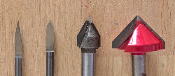
V-bits: 30 deg and 60 deg (1/8" shank); 60 deg and 90 deg (1/4" shank)
With a straight end mill (flat or ball-nose), the width of cut is limited by the radius of the tool. If we are using a 3/8” end mill, there is simply no way to cut a 1/4” slot, and all our inner corners will have a 3/8” radius. Not so with a V-bit. By varying the depth of cut, we can mill V-shaped grooves as narrow as the tip of the V-bit: possibly 0.1 mm, or 0.004” (4 thou). Our tool will rise or plunge depending on the required width of cut.
On the other hand, the depth of cut is determined by the tool angle. Also, keep in mind that very narrow widths of cut will also be very shallow, and thus hard to see. A 90 degree V-bit cutting a 0.1”-wide line (2.54mm) will produce a cut that’s only 0.05” deep (1.27mm). That’s where a 30 degree tool comes in. Thanks to the more acute angle, the tool will cut deeper for the same width: almost 0.2” (4.74mm).
This is why it’s best to have multiple V-bits with different angles. The most common ones are 30, 60, 90, and 120.
90 degree V-bits are also great for making miter joints, since they create two 45 degree edges:
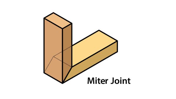
90 degree V-bit can be used to make miter joints. Image source
Advanced VCarve
With regular V-carving, you can’t choose the depth of cut. Very wide cuts will always have a very deep groove, which you may not want, and V-carving an area that’s wider than the bit can be very disappointing:
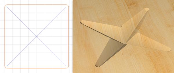
V-carving a 4x4" square results in a star... not what we want.
Carbide Create’s advanced V-carving fixes this.
- Firstly, it limits the maximum depth.
- Then, the bit follows the outline of the shape, rather than looking for the middle point between edges.
- Lastly, you can optionally use a flat bit to mill out the remaining material that was not milled by the V-bit. The pocket will be milled first, and then you’ll have to change the tool to a V-bit to cut the outline.
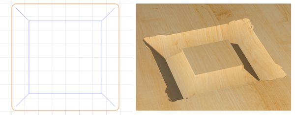
Advanced V-carve correctly follows the shape outline, never cutting deeper than specified.
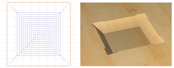
Optionally, advanced V-carve can use a flat bit to pocket the inside area to the specified depth.
Watch out though. If you choose to pocket the inner area, you will have to zero the bit after every tool change. Carbide Create’s G-code pauses the machine with an M0 command (if set to export Grbl-compatible G-code), which lets you change the tool and zero it before manually resuming. I recommend using a G-code sender that lets you resume from an arbitrary G-code line, for example Candle, so that you can abort the job and then resume from the line with the M0 command.
Ideally, you’ll want to have a bit-setter such as this one and a macro set up in your G-code sender to probe the new tool. Then, when the machine is paused by M0 and waiting, just change the tool, run the macro, and then resume.
Generating G-code
9. Preparing for exporting
From View > Select Post Processor we can tell Carbide Create to adjust the G-code for the kind of machine we are using.
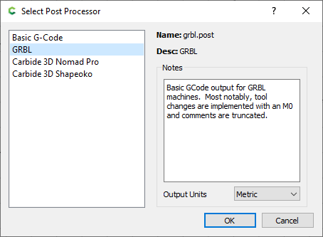
You’ll probably want to select the Grbl post processor if your CNC router is running Grbl (e.g. the 3018 Pro and other Sainsmart CNCs, Shapeoko machines, or routers using OpenBuilds’ BlackBox controller), although I did not notice any difference between G-code exported with “Basic G-code” or “GRBL”. With these two post processors, tool changes (M6 command) are replaced with machine pauses (M0).
On the other hand, the Nomad and Shapeoko post processors use M6 for tool changes issue a G53 command. G53 indicates a move according to the machine coordinate system, which requires limit switches. For example, G53 G0 X0 Y0 Z0 will home the machine.
Using the G-code
If you are using Carbide Create V6, you can export the G-code directly to a file as described below.
On V7, you’ll have to use Carbide Motion as the G-code is tucked away inside the save file itself (“projectname.c2d”).
10. Saving and previewing the G-code (CC V6)
With all this done, we are ready to export the G-code! Carbide Create will create an .nc file, which is a simple plaintext file with a list of G-code commands. It can be opened in any text editor like Notepad (Windows), TextEdit (Mac OS), or VS Code.
However, I always make sure to preview the G-code before running it. Remember: CNC machines always do exactly as they are told… even when the CAD/CAM user screwed up. We want to avoid any mistakes in the G-code by running a realtime simulation.
My favorite program to simulate G-code is Camotics, which is free and open source.
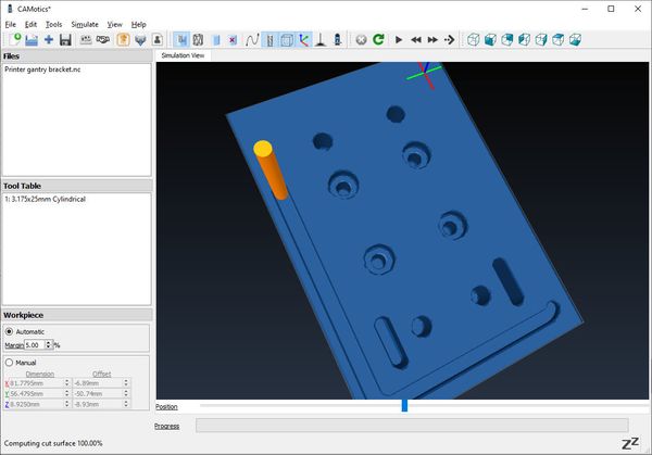
Camotics can simulate the entire cutting operation from start to finish.